Table of contents
Lab 2 - Rainbows and Capacitive Touch!
Last time was all about getting up and running. This time we’re going to add in another library (rainbowio) and learn about capacitive touch.
Lab Signoff
Before you leave for the day, (minimally) show me:
- Capacitive touch working (i.e., your contacts on the side demonstrate some response to touch)
- Rainbows happening on the LEDs when you press a button
First - back up your old code
I am going to make the assumption that your code from Lab 1 either exists as code.py or the required naming structure. One thing that I find helpful is to make a folder on the device called backups, and to move my old code in there.
Remember, the file that runs is code.py, so whatever is named that will be active every time you power up the device.
MORE COLORS
It is good to understand how RGB color works, though it is also good to leverage libraries that take care of all the low-level efforts needed (though, don’t import things unless if you absolutely need them - again, memory constraints)!
Remember, RGB = RED-GREEN-BLUE, where each color ranges on [0-255]. So, black = (0, 0, 0), white = (255, 0, 255), yellow = (255, 255, 0), etc.
Let’s go ahead and add in some light shows to demonstrate why programmable LEDs are just the niftiest thing in the world.
Get setup (again)
New code.py file! At the top, import the following libraries:
from time import sleep
import board
import neopixel
import gc
import digitalio
We also need to setup our Neopixels and buttons in the same way. Note - the named colors is slightly tweaked to be closer to the Adafruit example that we’ll be using.
# initialize neopixels
NUM_LEDS = 10
pixels = neopixel.NeoPixel(board.NEOPIXEL, NUM_LEDS, brightness=0.01,auto_write=False)

# named colors
RED = (255, 0, 0)
YELLOW = (255, 150, 0)
GREEN = (0, 255, 0)
CYAN = (0, 255, 255)
BLUE = (0, 0, 255)
PURPLE = (180, 0, 255)
WHITE = (255, 255, 255)
OFF = (0, 0, 0)

# set pixels to off initially
for i in range(NUM_LEDS):
    pixels[i] = OFF
pixels.show()

# setup buttons
btnA = digitalio.DigitalInOut(board.BUTTON_A)
btnA.switch_to_input(pull=digitalio.Pull.DOWN)

btnB = digitalio.DigitalInOut(board.BUTTON_B)
btnB.switch_to_input(pull=digitalio.Pull.DOWN)
BTN_TIMER_DELAY = 15
btn_timer = 0

done = False
while not done:
    if btnA.value and btnB.value: # Both buttons pressed - exit
        done = True
    else:
        if btnA.value and btn_timer == 0:
            btn_timer = BTN_TIMER_DELAY

        if btnB.value and btn_timer == 0:
            btn_timer = BTN_TIMER_DELAY

    # Handle button cooldown
    if btn_timer > 0: btn_timer -= 1

    sleep(.01)
    gc.collect()

print("Program done - exiting.")
Import the rainbowio library
Fortunately, this library should already be installed when you got CircuitPython setup.
To your list of imports add:
from rainbowio import colorwheel
We’re going to be using code from Adafruit on this one, as they have a pretty interesting set of functions for doing things with LEDs.
This is the link in question: Adafruit CircuitPython NeoPixel
You are more than welcome to define your own functions as well! Be creative!
This very well may be the first functions we use in class! These ideally are placed above where they are first executed - typically I put them below the import statements.
I don’t know if this is a “recent” thing from CircuitPython, however you need to define your functions before you use them (similar to C). You can put your function definitions at the top, under your import statements. (Normal Python doesn’t typically care where you put your functions).
Code from Adafruit:
def color_chase(color, wait):
    for i in range(10):
        pixels[i] = color
        sleep(wait)
        pixels.show()
    sleep(0.5)


def rainbow_cycle(wait):
    for j in range(255):
        for i in range(10):
            rc_index = (i * 256 // 10) + j * 5
            pixels[i] = colorwheel(rc_index & 255)
        pixels.show()
        sleep(wait)


def rainbow(wait):
    for j in range(255):
        for i in range(len(pixels)):
            idx = int(i + j)
            pixels[i] = colorwheel(idx & 255)
        pixels.show()
        sleep(wait)
But hold on - what is the
colorwheelfunction? If we look it up directly in the library API it just says this is an implementation of the Ccolorwheelfunction - not helpful.However, there’s a nice writeup on this website:
The
colorwheel()function takes a single value 0-255 hue and returns an (R,G,B) tuple given a single 0-255 hue. It’s not a fullHSV_to_RGB()function but often all you need is “hue to RGB”, where you assumesaturation=255andvalue=255. It can be used with neopixel, adafruit_dotstar, or any place you need a (R,G,B) 3-byte tuple.Essentially, we’re getting an RGB tuple from the “position” on a color wheel.
Each of these functions has a wait parameter - this is how long in-between changes. Essentially, you call one of the functions and it runs for the entire cycle. You can try it by calling one prior to our forever loop.
For example:
rainbow(0.01)

done = False
while not done:
   ...
Try the other functions as well! In the next section we’ll use our buttons to handle the show.
Start the show on a button press
We have two buttons, let’s use button A to start the rainbow show and button B to start the rainbow_cycle show.
Inside our button handlers (don’t remove setting the btn_timer value!):
if btnA.value and btn_timer == 0:
    rainbow(0.01)
    btn_timer = BTN_TIMER_DELAY

if btnB.value and btn_timer == 0:
    rainbow_cycle(0.01)
    btn_timer = BTN_TIMER_DELAY
At the bottom of our loop (above the call to sleep) add the following so that the colors are shut off once the cycle is complete:
# Set our LED colors and display them, if enabled
for i in range(NUM_LEDS):
    pixels[i] = OFF
pixels.show()
At this point, you should have two color shows happening on a button press and once complete the device should go dark.
Try playing with the timings! And try out color_chase as well!
Capacitive Touch
Here is the Adafruit reference for this section
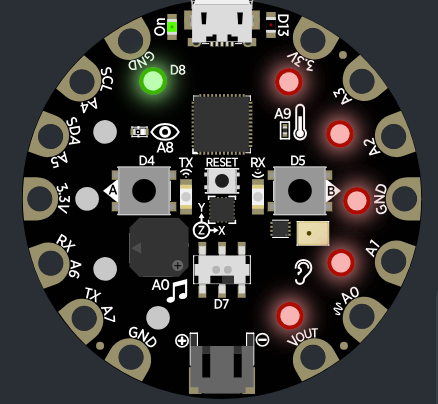
Now it is time to talk about those golden/brassy rings around the side. Those are pins that can be used for input and output (or, why we have the alligator clips).
Interestingly, they also support something called capacitive touch. Essentially, these ports will allow you to make a connection simply by using your finger (or some other object which will transmit the signal, say, a banana).
Without delving into the details, this means we have an additional seven options for providing input to our device.
A0 is not a capacitive touch input.
Here are the locations on the board - note the labels:

Neat, but how do we use them? We’ll need a library to handle the touching parts:
import touchio
Then, below where your buttons are defined, add the following so that we have access to all of our capacitive inputs:
# capacitive touch
touch_A1 = touchio.TouchIn(board.A1)
touch_A2 = touchio.TouchIn(board.A2)
touch_A3 = touchio.TouchIn(board.A3)
touch_A4 = touchio.TouchIn(board.A4)
touch_A5 = touchio.TouchIn(board.A5)
touch_A6 = touchio.TouchIn(board.A6)
touch_TX = touchio.TouchIn(board.TX)
You can use it the same way you would with buttons (including delay if you wish):
if touch_A1.value:
    print("A1 was touched!")
If you really wanted to, you could connect one of your alligator clips to A1 to see if that works…
Let’s bring it all together.
Currently, your buttons are kicking off LED lightshows. Leave them to do that for now.
In your forever loop:
Set the lights to a color of your choosing (perhaps, create a variable to store the
current_colorand set each of thepixelsto that color at the end of the loop).Have one side of your touch inputs lower the brightness and the other side increase the brightness.
- Recall that changing the brightness can be done in-line:
pixels.brightness = value, wherevalueis within[0.0, 1.0] - One thing that might be helpful is to create a global variable that sets the speed of your incrementing/decrementing of the brightness
- For instance,
increment_value = 0.01andpixels.brightness += increment_value
- For instance,
- Double-recall that you should check to make sure that
valueis never less than0.0and is never greater than1.0
- Recall that changing the brightness can be done in-line:
A journey of self-discovery
One thing that you might be wondering is how to write data to file as you have in other programming sessions. For instance, these are our eventual IoT devices … we want to log data, correct?
Embedded devices are tricky at times and the Bluefruit is no exception. It is possible, however not very practical for us.
This link talks about how to setup file writing, but in essence what is going to happen is that:
- You will need a special file to run at startup
- You’re not going to be able to live-edit your code and see changes - you’ll have to pull power and do a hard reset (as the special file will only run once).
- There’s not a lot of space on the device anyway - there’s probably a better way to handle data logging.
Nothing to formally do in this section, but I want you to understand the limitations of embedded devices. Part of your homework will be reflecting on this topic.
Homework Extensions
What you should have by the time you’re done with the lab is:
- The LEDs showing a color of your choice
- Buttons A and B starting different rainbow light shows
- Touch inputs on one side lower the brightness and raising the brightness on the other side
Based on the examples, there are a few options we could sort through. Wouldn’t it be neat if it were user-selectable? We have 3 rainbow functions.
We’re going to use LEDs 0-4 for the homework updates (3 and 4 will be
OFF), and LEDs 5-9 for our previous brightness changer.
So, at the end of each loop, set pixels 0-4 to
OFF, and pixels 5-9 to yourcurrent_color.
Add a counter to track the ‘currently selected’ function. rainbow should be 0, rainbow_cycle should be 1, and color_chase should be 2.
While the Circuit Playground is not doing anything, the corresponding LED should be lit up with a color of your choosing. For example, if rainbow_cycle is selected, then pixels[1] should be the only LED on.
There should only be 1 LED lit at a time in the 0-4 range and all LEDs lit in the 5-9 range, with the specified brightness based on your touch inputs, like this:
Change your button presses to do the following:
When
button Ais pressed, the counter should be incremented to “cycle” through the available options. Ensure that you do not go over the number of available options (e.g., the fourth LED should not be on)!When
button Bis pressed, execute the current color function.When both buttons are pressed, exit (as usual).